Probing PDM: MP45DT02 and STM32F407
STM32F4 Discovery Boards
You may or may not be aware that the STM32F407 evaluation boards (STM32F4DISCOVERY / STM32F407G-DISC1) are kitted out for audio processing. They come equipped with with a MP45DT02 MEMS microphone along with a CS43L22 DAC.
For a while now I’ve been interested in getting the MP45DT02 up and running. After putting it off with one excuse or another, I recently found the time (and motivation) to experiment with it.
Introduction to Pulse Density Modulation (PDM)
The MP45DT02 isn’t what I consider a “standard” microphone. Granted, I have no previous experience with low level interfacing with audio devices, but when I think of a microphone, I envisage a device which produces an analogue output signal. Through sampling with an Analogue to Digital Converter (ADC), it is then possible to acquire a stream of Pulse Code Modulation (PCM) samples.
This MP45DT02 is a MEMS microphone however, which instead of outputting an analogue waveform produces a stream of digital Pulse Density Modulation (PDM) samples. Each individual bit in this stream is a sample. The amplitude of the sampled audio waveform can be inferred from the “density of the pulses”, i.e. as the amplitude of the sampled signal increases you will find a larger cluster of 1’s in the PDM stream.
How can we use PDM? Since the density of “1’s” is proportional to the audio amplitude we can simply start by taking a moving average of the PDM samples. E.g. consider averaging a series of PDM samples taken in:
- a quiet environment:
avg([0,0,0,1,0]) = 0.2 - a noisier environment:
avg([1,0,1,1,1]) = 0.8.
These values should hopefully feel like more appropriate representations of an analogue waveform under such conditions.
However, a moving average of the PDM stream is still going to be an average of 1-bit samples. In order to provide as much useful information as possible in each averaged sample, we want to average a unique set of PDM bits each time. In order to achieve this we need to oversample the PDM microphone by the same factor. In the above example we would sample at 5 times the desired sampling frequency, calculate a moving average, then proceed to throw away all averages except every fifth value (this concept of throwing away output samples is known as downsampling). E.g. we desire a 8 kHz output waveform, so with our 5-to-1 averaging method we would need to sample the PDM microphone at 40 kHz.
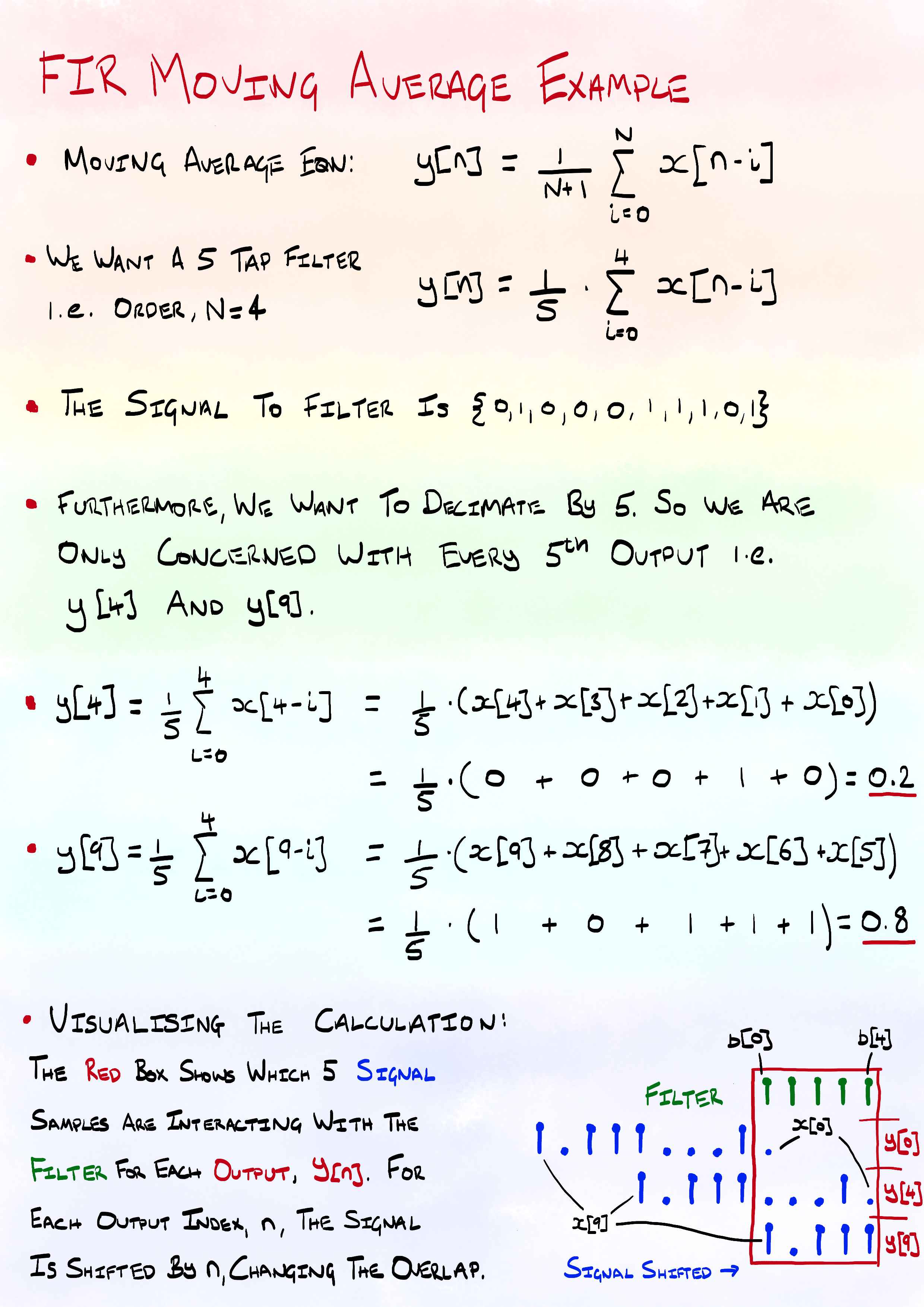
A moving average is a basic form of a Finite Impulse Response (FIR) filter. In the above case it was a 5 tap filter, where every scaling coefficient is equal to 1/5 = 0.2. As with any form of signal sampling, it is a good idea to stick a Low Pass Filter (LPF) after the sampling process to limit aliasing effects. Similar to a moving average, LPFs can be implemented with a FIR filter, and by using a LPF we do not require to use a moving average. The difference being the LPF’s coefficients must be carefully chosen so that the filtering process will reduce the effects of any high frequency components in the stream.
In case anyone was interested, I worked through the same 5 tap, decimate by 5 example discussed above except using the more formal FIR equation.
Unfortunately, the above example is rather simplistic, and using 5 samples to calculate the average is not enough to produce a reasonable quality output signal. Considering the simple moving average filter again, with 5 samples we can only obtain the levels 0, 0.2, 0.4, 0.6, 0.8, 1.0. This leads us to another maths filled Wikipedia page: Quantisation Noise. More taps will be required to produce more granular signal levels in the output signal. This comes at a cost however, a higher PDM sampling rate and more taps both require more CPU cycles for processing.
It is worth noting the number of taps in the FIR filter can be equal to, or greater than the desired decimation factor. A good reason reason for a greater number of taps is to improve the filter’s attenuation of high frequencies.
To summarise (TLDR); there are three main steps to convert a PDM stream to a more familiar (and useful) PCM stream. This can be reduced down to two steps by combining steps 2 and 3, since we only need to perform calculations for the output values we intend to keep. To throw in some additional technical lingo, the combination of filtering to remove aliasing and downsampling is known as decimation.
- Oversample the PDM microphone by factor x
- Low Pass Filter the samples (number of taps >= x)
- Downsample the filtered data by factor x (keep only every x filtered sample)
Using I2S to sample MP45DT02
The MP45DT02 is designed to allow stereo audio capture; two of the devices can operate simultaneously, sharing a bus. If pin 2, (labelled LR) is connected to GND the MP45DT02 is placed in “left” channel mode. In this mode, a sample is latched to the data output pin (PDM) on a falling edge of the clock. On the rising clock edge, the output is set to high impedance. If the LR pin is connected to Vdd then the device operates in “right” channel mode and the MP45DT02 latches it’s sample to PDM on a clock rising edge, setting the pin to high impedance on the falling edge of the clock. The timing diagram below shows the behaviour.
MP45DT02 Timings
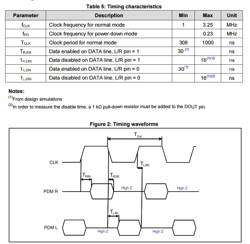
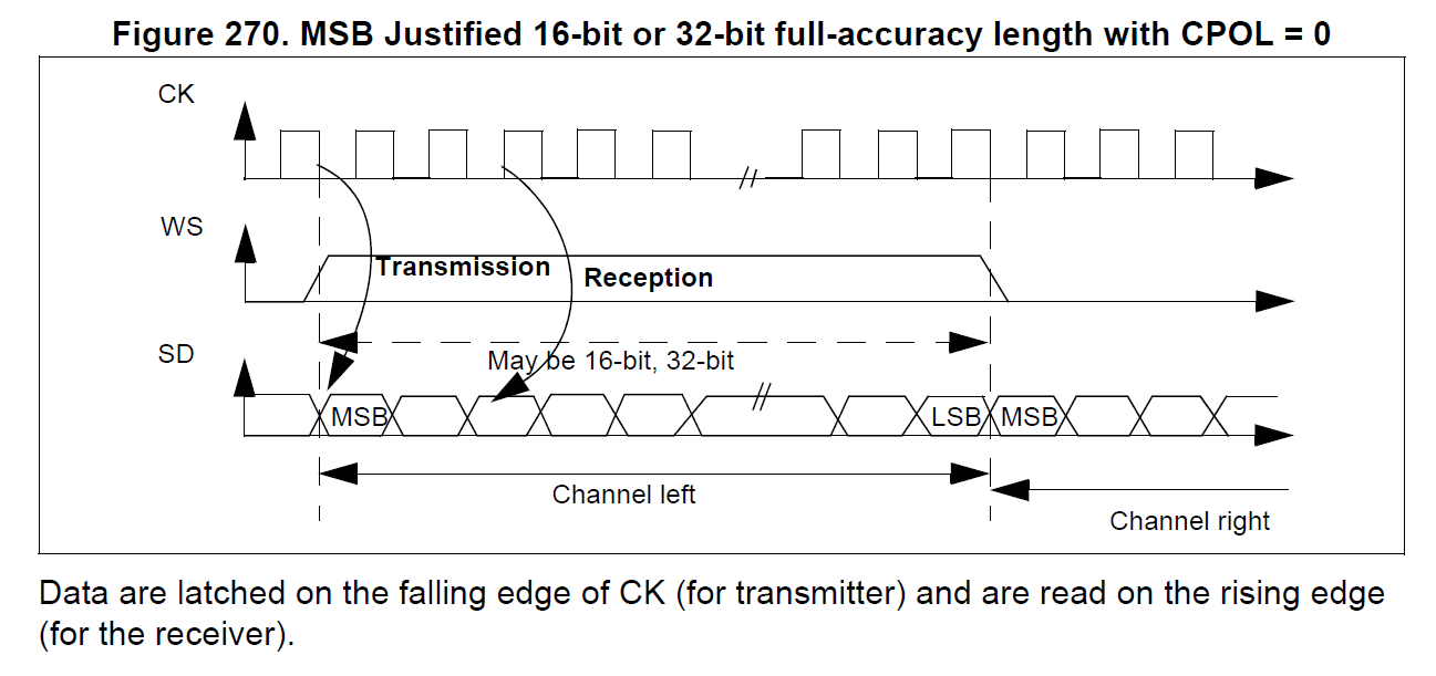
On the STM32F4DISCOVERY, the LR pin is grounded so the device permanently operates in “left” channel mode; the data being valid when the clock is low. The MP45DT02 is thus expecting to be sampled between clock transitions, when the data line is stable. This is quite different behaviour from the I2S protocol (which appears to be most common method to interface to this device). In I2S the data is loaded to the line on the falling edge of the clock, to be valid for sampling on the rising edge. The I2S protocol can be seen in the diagram taken from ST’s datasheets below.
STM32F4 I2S
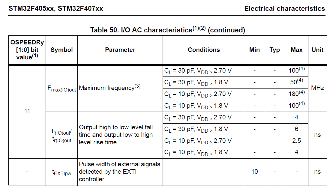
It appears to me using I2S to sample the MP45DT02 is somewhat of a hack. From the timing information provided in the MP45DT02 datasheet the microphone can take up to 16 ns to clear the data from the PDM pin on a clock rising edge. The rise time of STM32F407 clock signal varies with load capacitance, but is rated at 4 ns at 30 pF. Presumably using I2S works because the vast majority of the time the MP45DT02 takes longer than 4 ns to react to the rising clock, allowing the STM32F4 to sample the data before it is cleared.
STM32F407 Electrical Characteristics
Working Example (CMSIS Filtering)
Below are the key values used in this example:
- I2S Clock: 1024 kHz
- FIR Filter
- Cut-off Frequency: 6 kHz
- Taps: 256
- Decimation Factor: 64
- Output: 16 kHz linear PCM Waveform
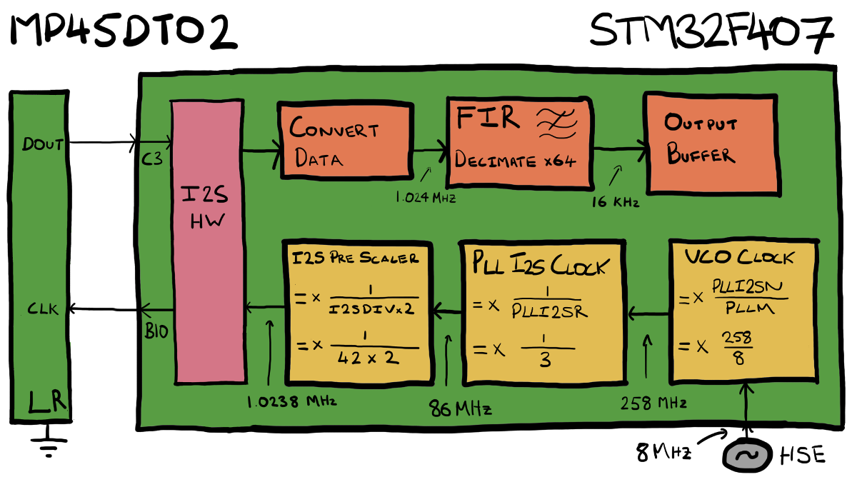
The following diagram provides an overview of this example. The orange boxes along the top show the various stages of data processing functionality, while the yellow boxes show the clock configuration.
Physical Connections
The connections between the STM32 MCU and the PDM microphone are listed below. The pins in use are controlled by the I2S2 hardware driver.
| STM32F407 Pin | MP45DT02 Pin |
|---|---|
| GPIOB 10 | CLK |
| GPIOC 03 | DOUT |
Clock Configuration
The required I2S clock is calculated by:
output frequency * decimation factor =
16 kHz * 64 = 1024 kHz
The below table shows the various stages of configuration which allow this signal to be output from the STM32F407.
| Signal | Formula | Substituted | Output Frequency |
|---|---|---|---|
| HSE | - | - | 8 MHz |
| VCO Clock | Clock Input * PLLI2SN/PLLM | 8 MHz * 258/8 | 258 MHz |
| PLL I2S Clock | VCO Clock /PLLI2SR | 258 MHz/3 | 86 MHz |
| I2S Pre-scaler Output | PLL I2S Clock / (I2SDIV *2) | 86 MHz / (42 *2) | 1.0238 MHz |
Incredibly Inefficient Filtering Implementation
The above information describes how the microphone is connected to the STM32F4. Now we’ll look at how PDM data can be retrieved and processed. There are four distinct steps to this process:
1. I2S Sampling
The I2S2 driver was configured to collect data from the microphone and fire an interrupt every 1 ms to notify that there is a buffer of I2S samples ready. Natively, this is stored in an array of uint16_t ’s. Each individual bit however is a PDM sample - i.e. there are 16 individual PDM samples per word.
2. Convert Data
For this test I wanted to keep things simple and use the FIR function from the CMSIS DSP library. In order to do this, the sampled data must first be converted into the format the CMSIS filtering functions require. In the case of the function arm_fir_decimate_f32(), this is an array of floats.
This conversion process involves moving every bit from the array of uint16_t’s provided by the I2S driver into its own floating point datatype. Initially I was interested in creating a linear 16 bit stream, so each 1 is scaled to be a INT16_MAX, and each 0 scaled to be a INT16_MIN.
This process is unfortunately processor and memory intensive (I did warn that this was an inefficient example). By implementing a bespoke FIR filter it should be possible to reduce some of the costs of this step. Considering memory usage alone, this step is converting 1 ms of 1024 kHz sampled I2S data into floats, requiring an array of 1024 * 4 bytes = 4096 bytes.
3. CMSIS FIR Decimating Filter
With the data now in an array of floats, the CMSIS filtering function can be used to filter and decimate the signal. The output of this stage will be an array of floats with 64x less elements than the input array.
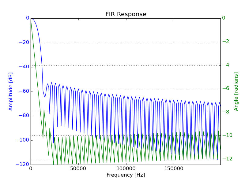
The FIR filter used for this step was a 256 tap Low Pass Filter (LPF) designed to have a cut-off frequency at 6 kHz. Like many aspects of this test, the number of taps and cut-off frequency were chosen fairly arbitrarily. The only criteria considered was ensuring the cut-off be less than the Nyquist Frequency of the downsampled signal (16 kHz / 2 = 8 kHz).
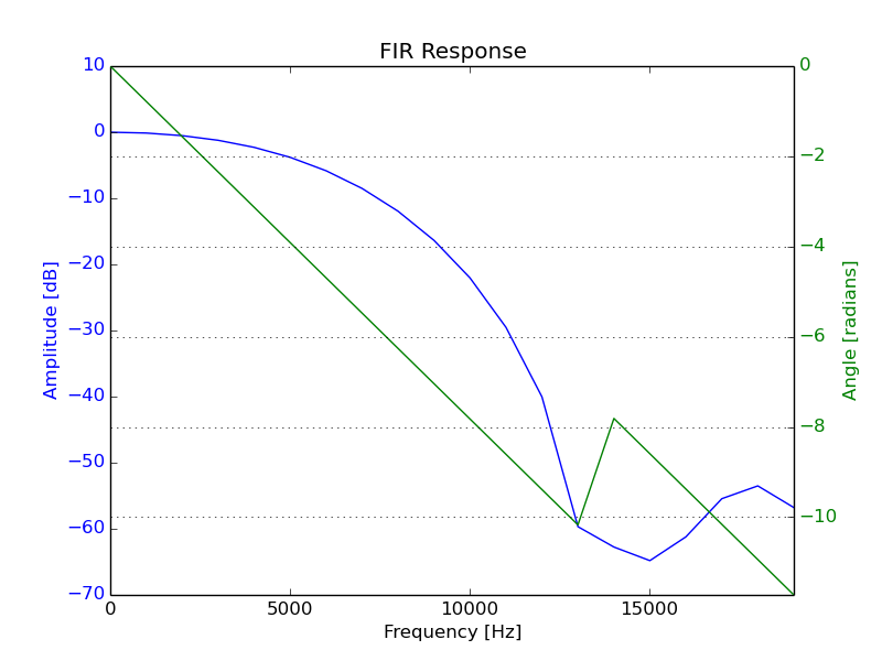
The same filter response, over a more relevant range:
4. Store in Output
Each 1 ms sample of the filtered data stream is slotted into a larger buffer, until 1.6 s of audio data has been collected. This number was chosen as it fills the remaining memory available on the MCU. With this buffer fully filled, the test is complete, and the data can be retrieved.
Testing
I’ll not lie, the initial testing process involved outputting a lot of random noise. Eventually however, the bugs were ironed out and a reasonable sounding recording made its way to my computer. To try and quantify that the code was behaving as desired, I wrote a Python script to generate a WAVE audio file containing several superimposed tones. With the STM32F4DISCOVERY placed beside a speaker, the WAVE file could be played and the recorded waveform taken from the STM32 compared to the generated one.
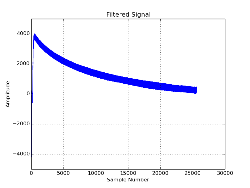
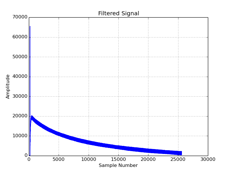
The comparison was achieved with a second Python script which performed an FFT of the recorded audio. All going well, the FFT should show the recorded signal was strongly comprised of the same tones which were played from the speakers. Below you can see the (boring) graph of the signal as well as the FFT.
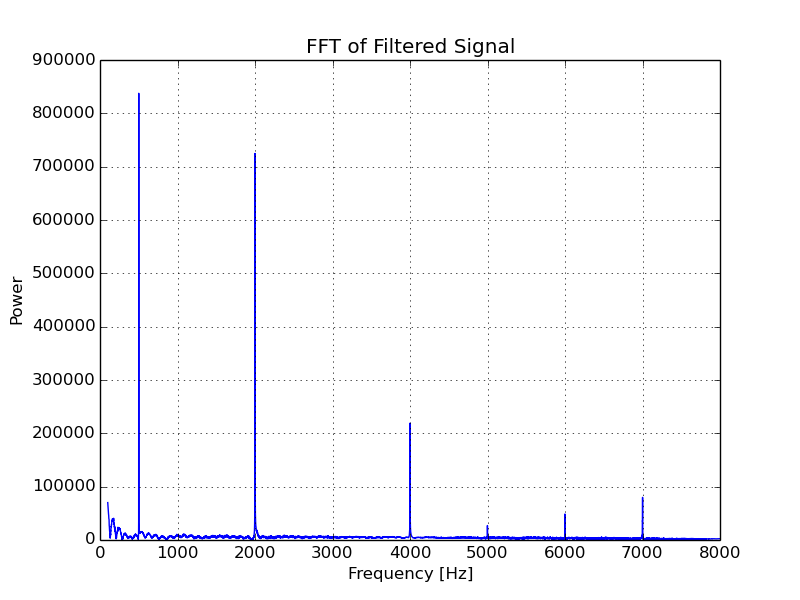
The audio file played from my speakers should have contained the following frequencies. The comment beside each describes what can be seen in the FFT of the signal.
- 500 Hz - Present in output (as desired).
- 2000 Hz - Present (as desired).
- 4000 Hz - Present (as desired).
The following tones were added to the test signal to test attenuation above the desired cut-off. Ideally, we don’t want to see (hear) them in the recorded signal.
- 7000 Hz - Clearly present (even though it is 1000 kHz above the desired cut-off).
- 10000 Hz - The alias of this tone can be seen at 6000 Hz.
- 11000 Hz - The alias of this tone can just about be seen 5000 Hz.
You can find the code and test scripts I used in the following github repository at the path test/mp45dt02_basic_cmsis_filtering. They were introduced at at the tag TEST_MP45DT02_CMSIS_1.
STM32 IIR Library
ST’s application note AN3998 - PDM audio software decoding on STM32 microcontrollers provides a helpful description of how to get audio from the MP45DT02. In it they make reference to a PDM filtering library they have produced, and distribute in binary form for GCC, Keil and IAR. This can be found in the STSW-STM32068 STM32F4DISCOVERY board firmware package.
Testing libPDMFilter_GCC.a
After getting CMSIS up and running I thought it would be a good idea to see how ST’s IIR filter performs. Unfortunately, I am unable to provide the source to this test. Version 3 of ChibiOS (the RTOS I used) is GPL’d so I cannot distribute it along with a closed source binary. I’ll note that it looks like in the future ChibiOS will have a linking exception added back in. This doesn’t mean ST’s license would allow me to distribute it - I haven’t looked at it in detail to check.
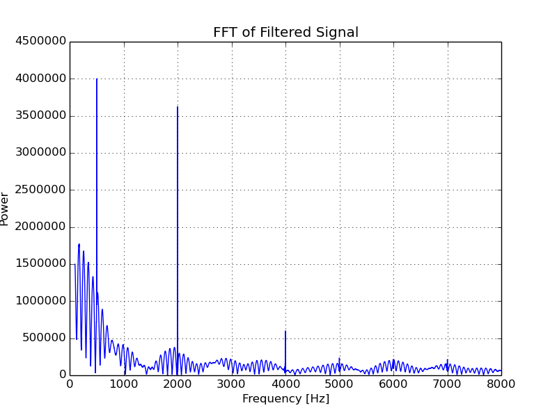
libPDMFilter was configured with similar parameters to the FIR filter above to give a LPF with a cut-off frequency at 6 kHz. Similar to the CMSIS example, the below graphs show the filtered signal and it’s FFT.
Quick Comparison of libPDMFilter and CMSIS
Note both the CMSIS and libPDM tests were compiled at GCC optimisation option -01 (no idea what libPDMFilter itself was compiled at, probably -02).
The libPDM output is notably not as “clean” as the FIR example. However, it outperformed my CMSIS FIR implementation by a significant margin.
libPDM required approximately 4700 CPU cycles per 1 ms sample to filter the raw PDM data into usable 16 bit values. The CMSIS filtering process on the other hand took approximately 17,000 cycles to expand the data from 1-bit samples to floats and 33,000 cycles for the actual filtering. This equates to approximately 50,000 of the 168,000 CPU cycles available in the millisecond between I2S interrupts. This is a significant portion of the available CPU time.
Furthermore, it is worth noting that the output of the CMSIS filtering is still in floats, so more cycles would be required to convert this into 16 bit values. I am not too concerned about this currently since there are two variants of the CMSIS filtering function which operate on Q15 fixed point data (as briefly discussed here) which may perform better when a 16-bit output is desired. I also really want to avoid looking into optimising filter performance for as long as possible.
Going Forward
Whether or not I actually use the CMSIS filter in my future project really depends on how many cycles the other components of the project require. I have no intention of using that big binary blob of libPDMFilter either, even if it is convenient.
There are still a few things I can try first before going forth and finding/writing a bespoke FIR filter.
1. Lower Cut-off Frequency
In my Googling, I stumbled across this interesting document, Sampling: What Nyquist Didn’t Say, and What to Do About It. In it, the author suggests that many of the “rules of thumb” I took away from my time in University are wrong (or possibly misremembered on my part). He also suggests that:
a good rule of thumb for intelligible speech transmission is that you need to transmit frequencies up to 3kHz
By lowering the cut-off frequency, there will greater attenuation at the Nyquist Frequency, reducing the energy of the aliased signals. The downside being may start to attenuate frequencies we actually desired.
2. Reduce the Number of Taps
Based on the above test, I have a sneaking suspicion that using a 256 tap CMSIS filter will be too processor intensive. With FIR filters, more taps creates a steeper roll-off, so fewer unwanted frequencies will sneak in. However, they also result in greater memory usage and require more CPU cycles.
Unfortunately for PDM data processing, the roll-off of the FIR filter is ultimately relative to the sampling rate. With a hefty 1024 kHz sampling rate, a 1000 kHz increment is only about 0.1% of the scale. It would take a large number of taps to get a roll-off steep enough to have a notable effect over this range.
All About Circuits Practical FIR Filter Design: Part 1 provides an approximation for calculating the number of taps based on desired signal characteristics. One of which is the desired stop band attenuation. Now there doesn’t seem to be a set in stone value for a “good” stop band attenuation although I have seen many examples use 40 dB (this is equivalent to attenuation to 0.01 % power).
Wikipedia suggests the stop band attenuation should at least be greater than 20 dB (1 % power). I’ll pick this lower value since I am going to be stingy with resources. I’ll also reduce the cut-off from 6 kHz to 3 kHz. Feeding these values into the tap estimate formula we get:
AdB = 20 dB
Fs = 1024 kHz
dF = (8 kHz - 3 kHz) = 5 kHz

N = 186.18 taps
This provides a starting number of taps for the future. Since I will likely be only processing voice, and won’t be needing anything of a high quality I probably could tolerate some aliasing and reduce this further if needs be.